

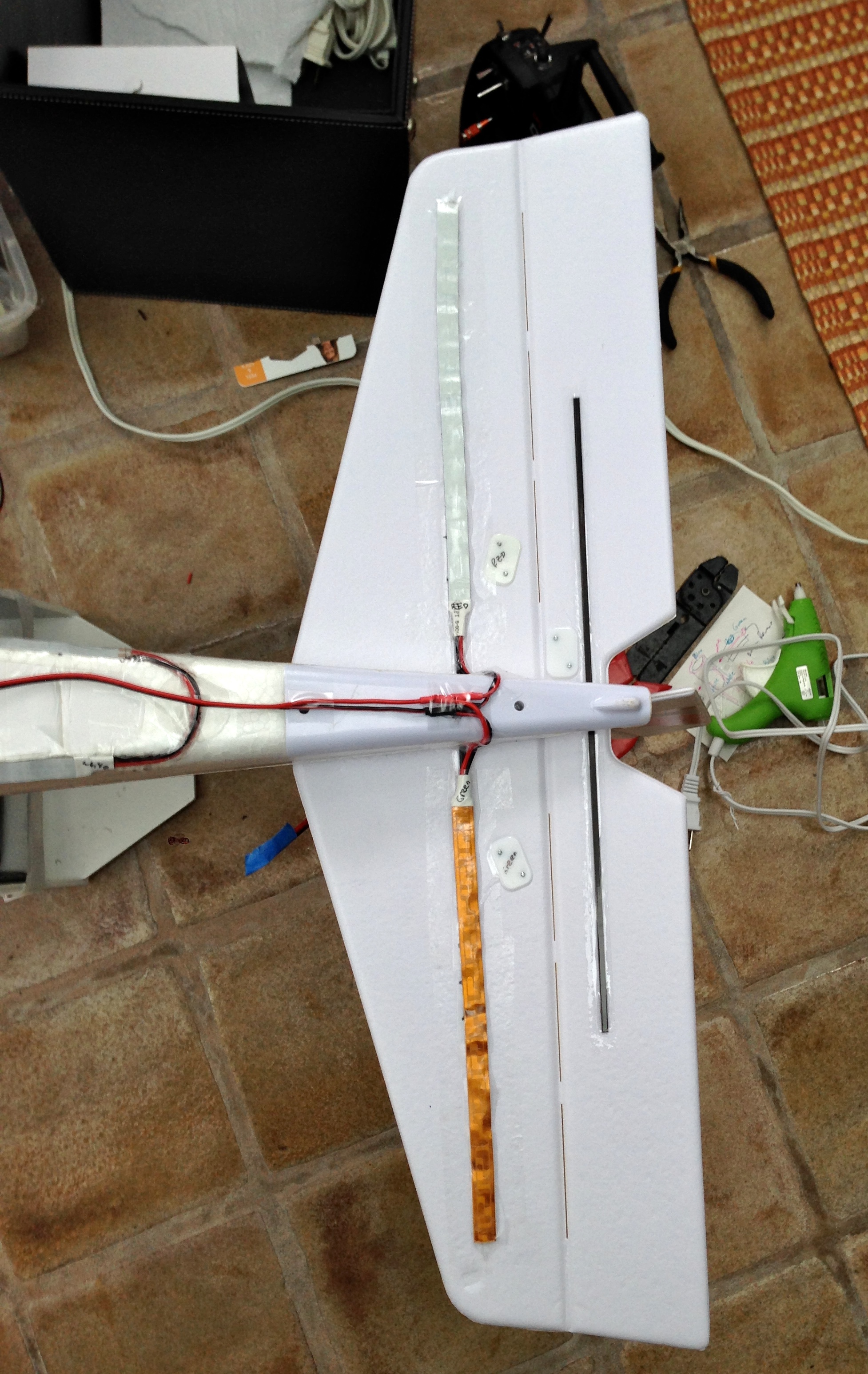
Apprentice S with green on right and red on left.
I’ve been intrigued by night-flying-capable RC planes lately. A few members from my local aeronautic modeler’s association flew planes with LED strips glued onto the wings and the fuselage, to allow them to see these planes clearly at dusk when other unlit planes would have appeared only as a nondescript black blob against the rapidly darkening sky.
I decided to resurrect my half-destroyed E-flite Apprentice S 15e, and endow it with abundant LED lights. But to my dismay I found no blog talking about such conversions. So I took pictures as I worked on the plane, whenever I remembered, with the goal of writing a great blog article when I was done.
Now I am done, but too exhausted to write an elegant prose on the process. So enjoy the picture story to follow… after you first check out a few useful pages on installing LED lights on RC planes:
- Night flying from Crash Test Hobby
- Video showing LED installation from Crash Test Hobby
- Great discussion about LED options including 5050 and 3528 LED strips
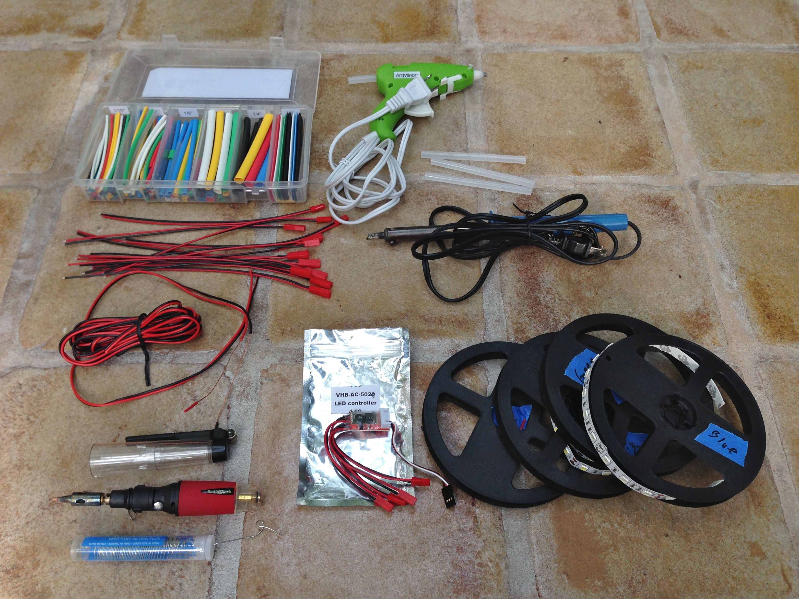
LED strip, LED Controller, connectors and essential equipment
Buy the brightest LEDs available. At this moment (2015-09) the best value is the 5050 LED strip such as this 1 meter white 5050 LED strip from Value Hobby. I bought two meters of white LEDs, one meter each of blue, green and red. I’d already measured and designed the light pattern tailored to the Apprentice – five meters was enough to lend adequate lighting.
The LED controller is powered directly from the 3S balance connector of the battery. It provides four independent JST RCY (BEC) output channels. A servo connector hooked up to the receiver allows one to switch light patterns from the radio transmitter between “all off”, “all on”, “sequential on” (channel 1, 2, 3 and 4), and “two alternating groups” (channels 1/3 vs 2/4).
I also got a bunch of JST BEC pigtails, both female and male. A dozen feed of red/black hookup wires completed the material list.
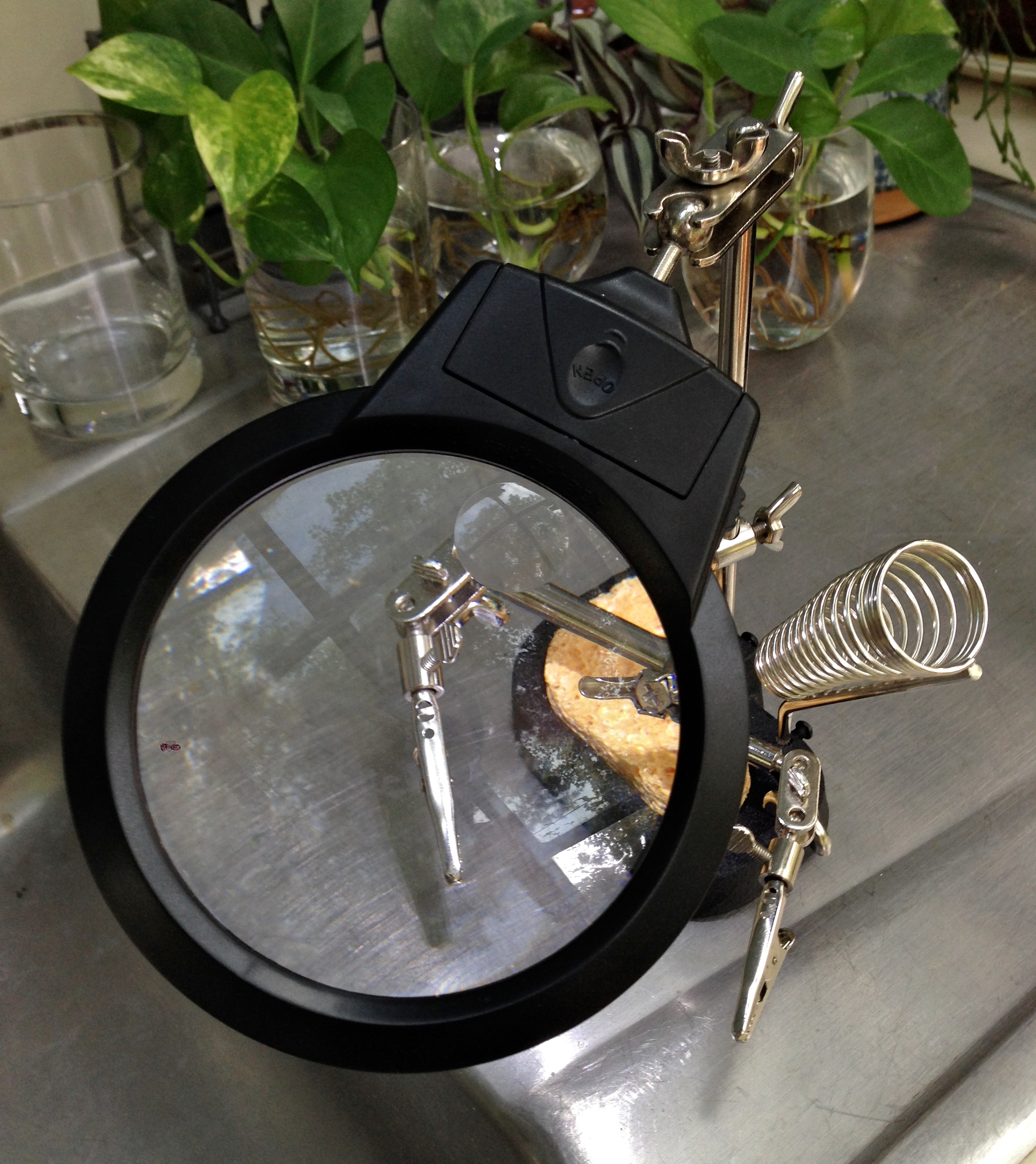
Helping hands with a magnifier
This was going to involve a lot of soldering. A pair of helping hands was invaluable. Without these I wouldn’t have been able to make solid connections. I used an old soldering iron with a rusted tip to burn a channel on the foam. The butane-powered soldering iron was most convenient with no wires to get tangled when I was concentrating on making good solder joints. The hot glue gun was a recent discovery of mine – it has replaced foam-safe CA glue and epoxy as my favorite glue for many hobby tasks.
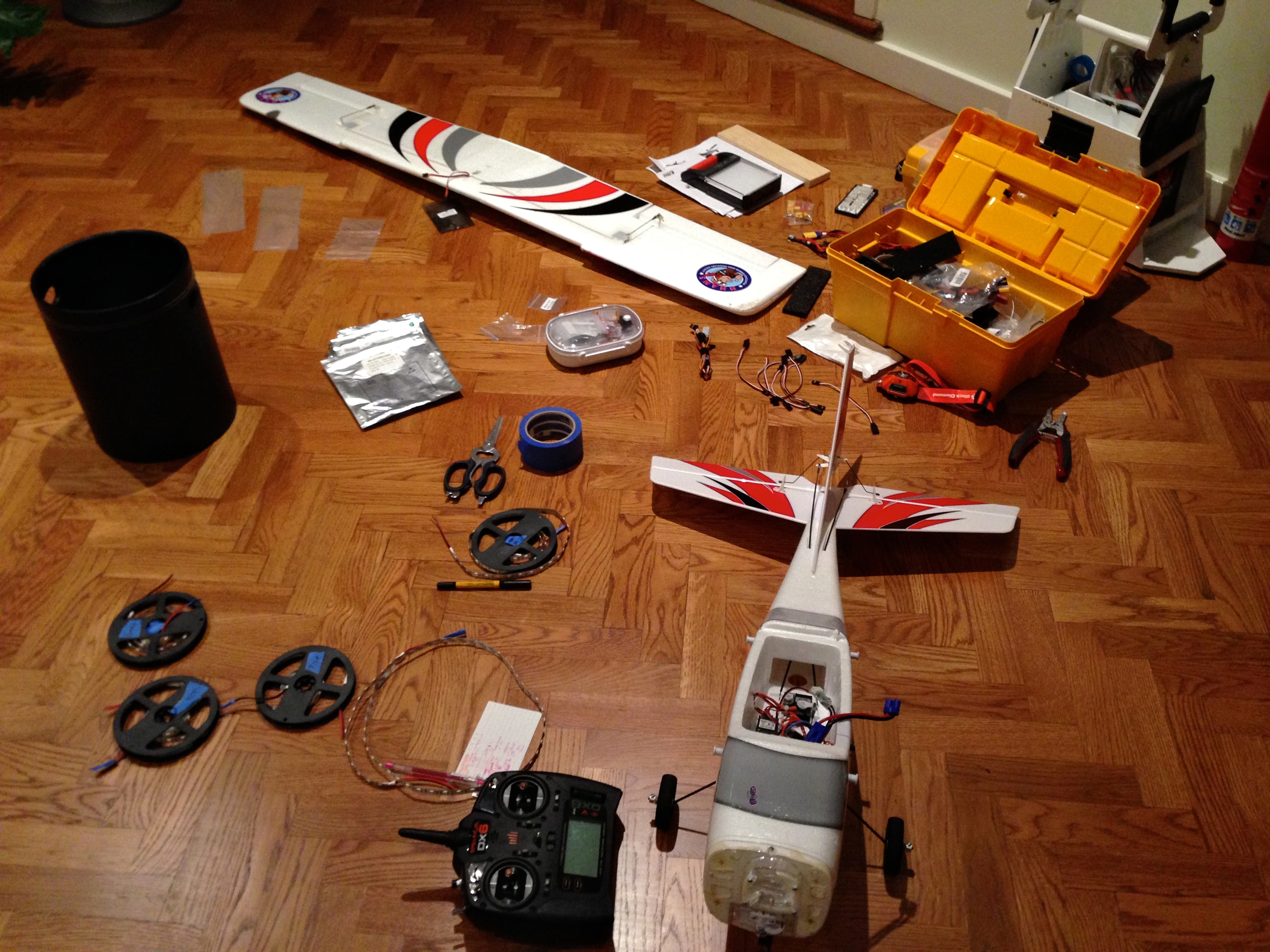
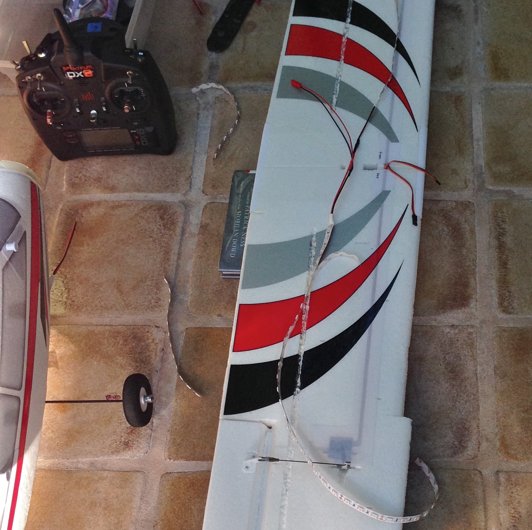
Figuring out where LED strips go on the Apprentice S
The LED strips and the controller arrived. I mapped out where these would go on the wing, the fuselage and the stabilizers. Then I cut them to length and taped them temporarily to the plane. Note how the Apprentice S was missing the entire cowl. One could see the remains of the motor mount on the firewall. This was a result of my flying the trainer in aggressive aerobatic maneuvers including knife edge. It would have been just a typical flying day, except that I mechanically trimmed the plane, then foolishly forgot to move the fuel tubing back to secure the clevis on the elevator control horn. The clevis tore lose and I was left without control of the most important surface. The wing would have broken into two piece were it not for the carbon fiber spar tube. I used epoxy to glue the broken wing back.
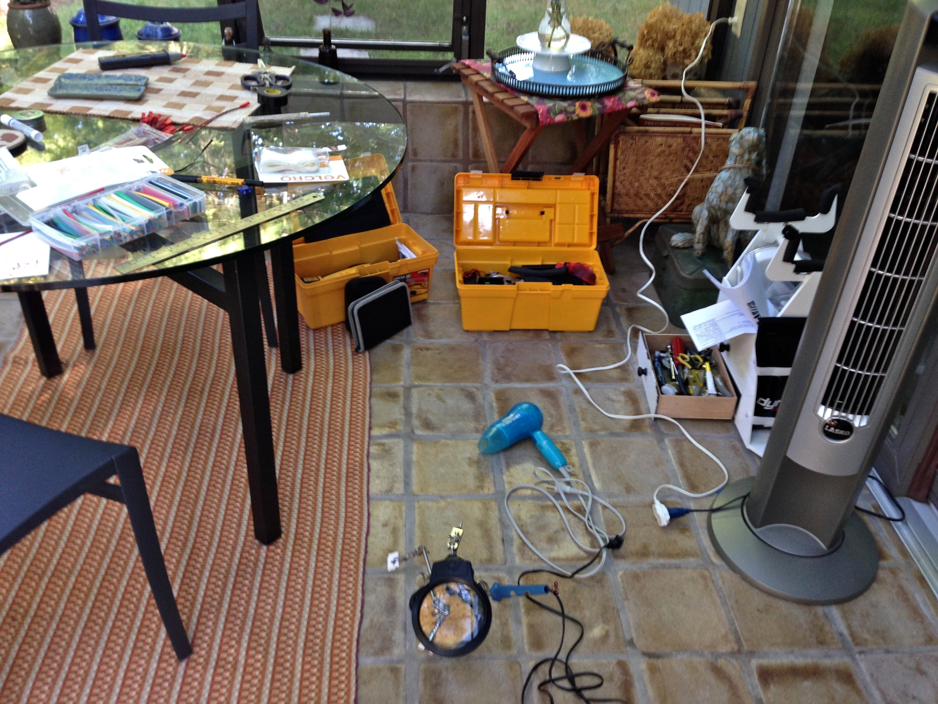
The author being relegated to a makeshift workshop due to burning smell
Someone in my household of two didn’t enjoy the burning smell of foam and solder. I had to establish a temporary workshop in the sunroom. Note the hair dryer used to shrink the heat shrink tubes around solder joints.
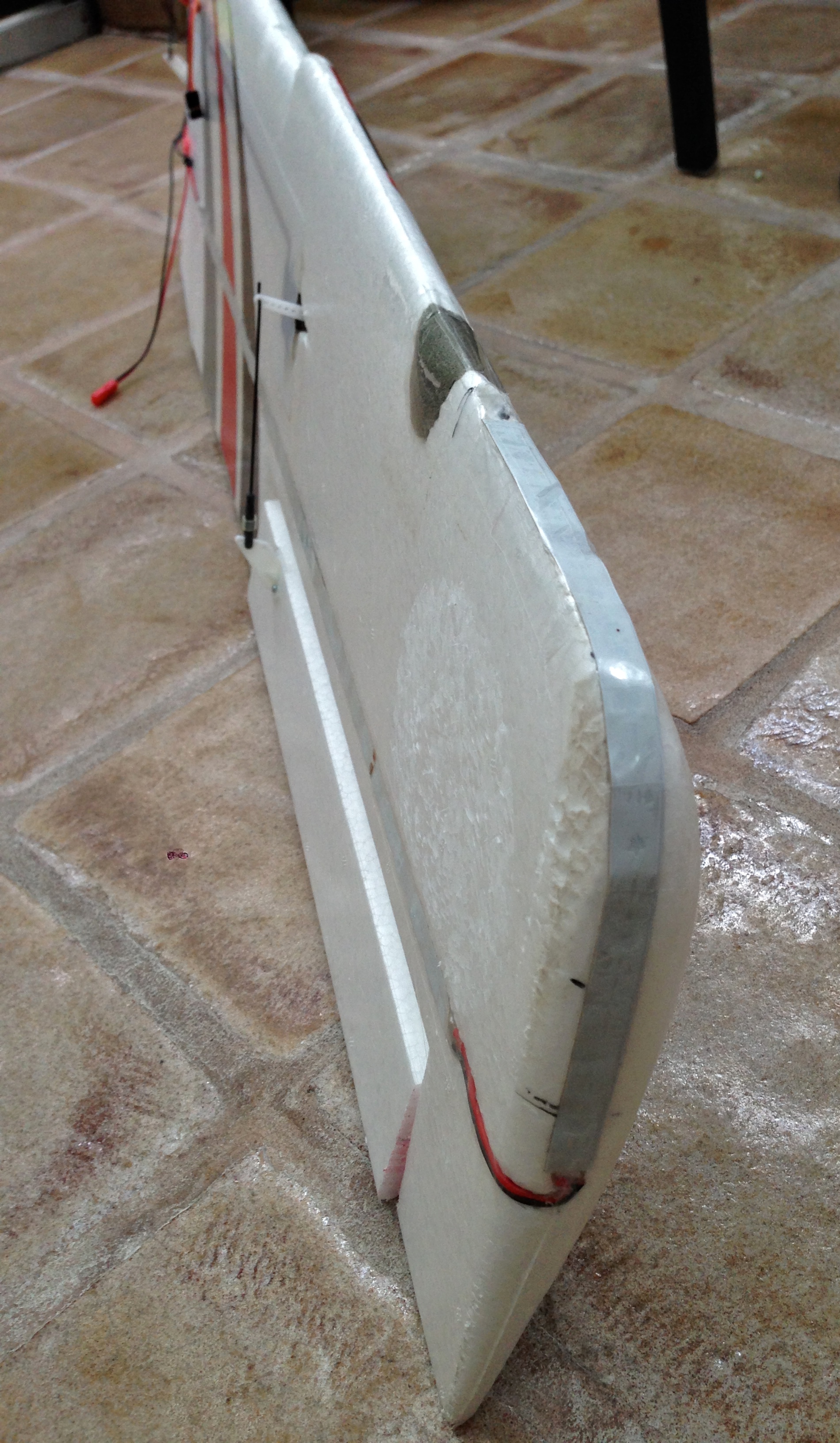
Burning a groove on the wing
I used the old soldering iron to burn a groove on each side of the wing to accommodate the an LED strip. I planned to install the LED lights facing the foam, to avoid blinding myself when I looked at the LED directly. I made the channel at the thinner part of the wing far below the spar, so that the lights shine through the foam, and can be clearly seen from the other side. I intended to install the LED light with its back flush with the wing surface to reduce air disturbance.
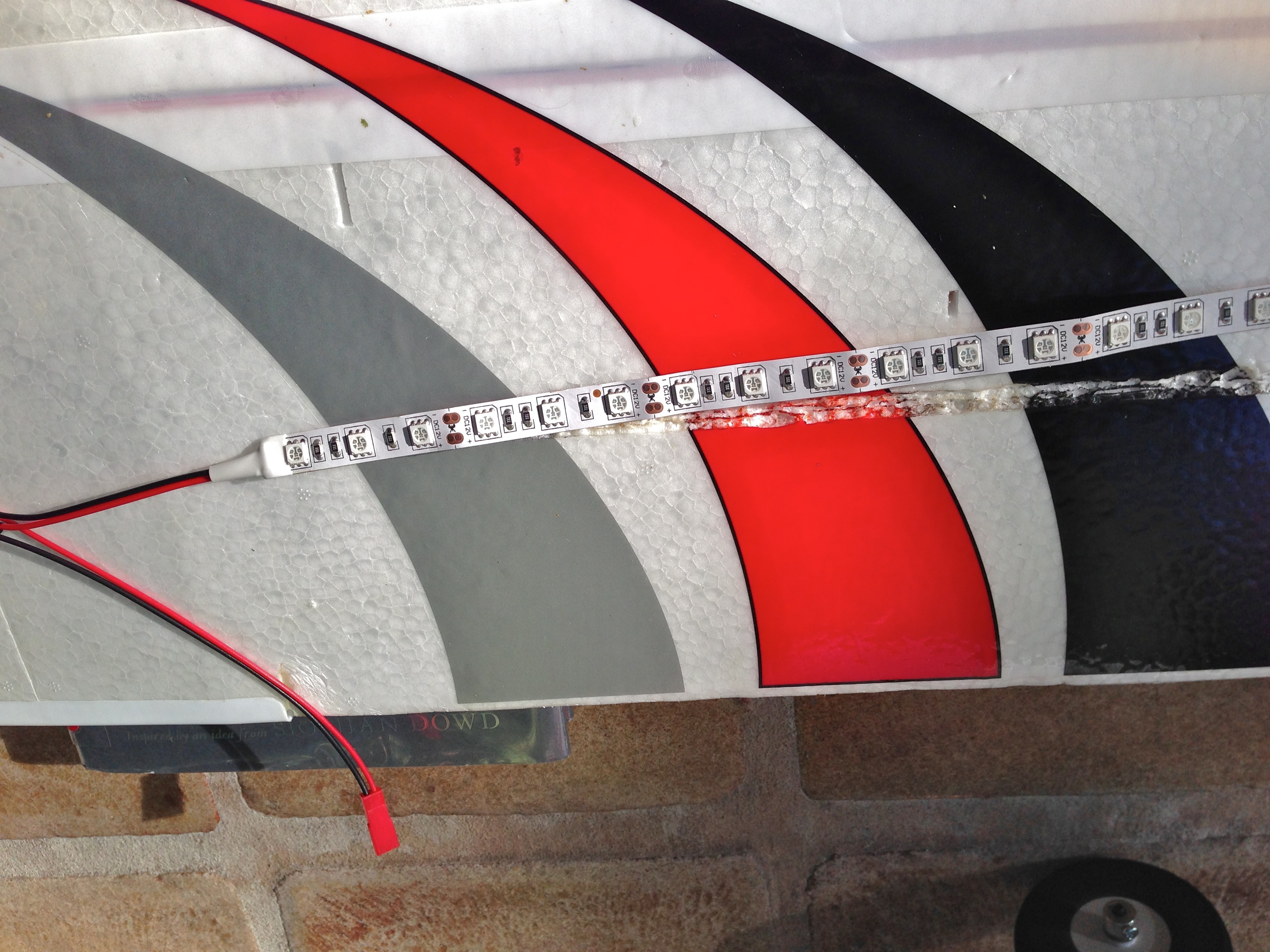
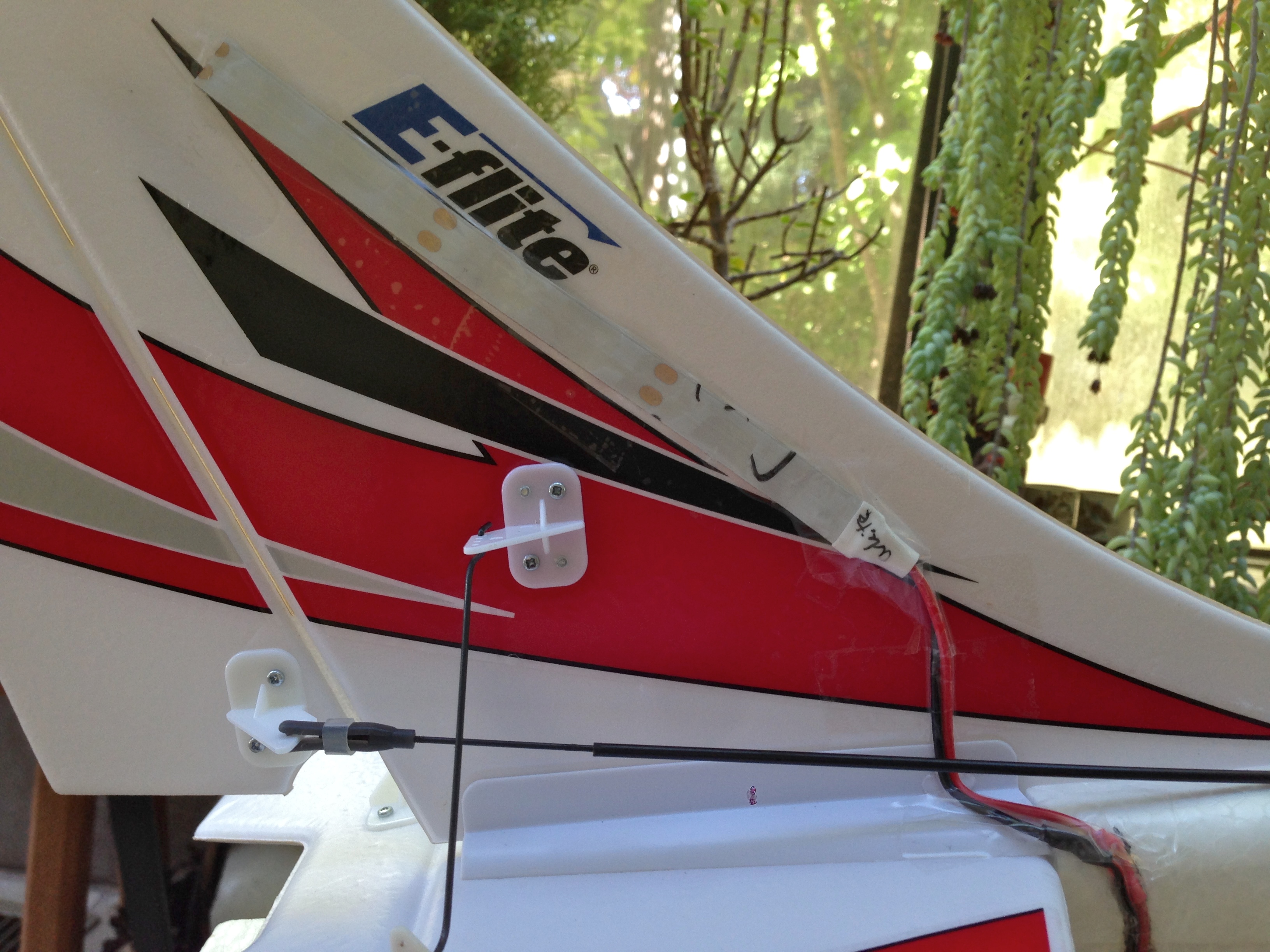
LED strip next to the burned channel
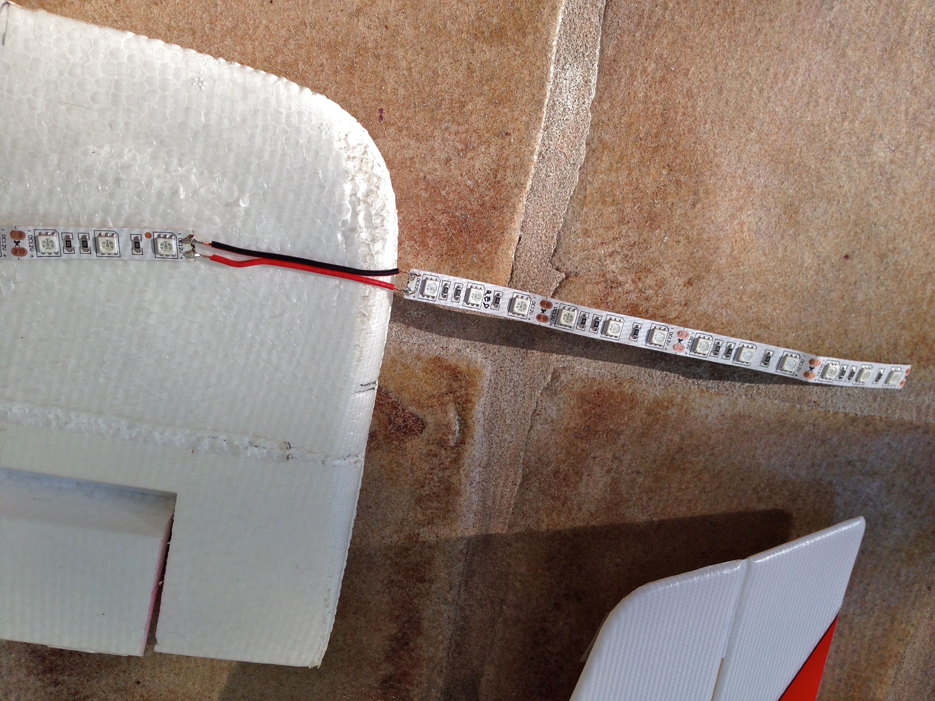
Extra LED strip to be wrapped around the forward corner of the wing
I figured that I needed some light to guide me when I flew the plane straight toward myself. So I used the solder to burn an indentation around the corner, and soldered a separate LED strip to the main strip via a stretch of silicon-wrapped hookup cable.
Forward corner of the left wring with red LEDs
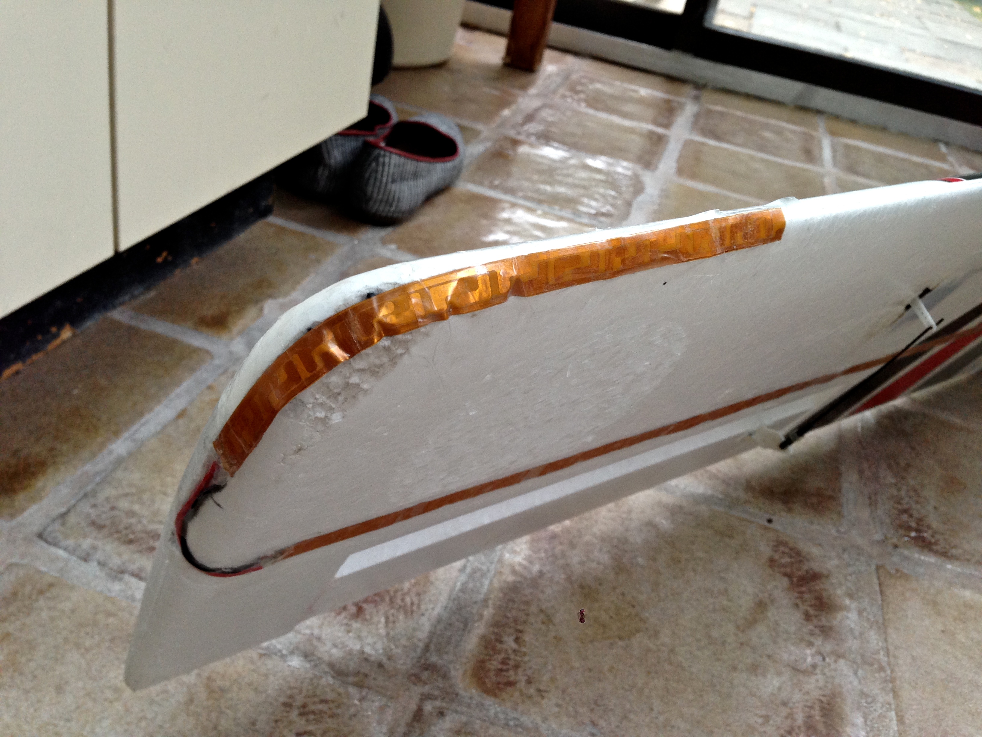
Forward corner of the right wing with green LEDs
For some reason each LED strip came with a different type of backing. The red LEDs came with a white metal back. The green LEDs came with a copper back. Following the standard navigation guides, I installed red LEDs on the left, and green LEDs on the right.
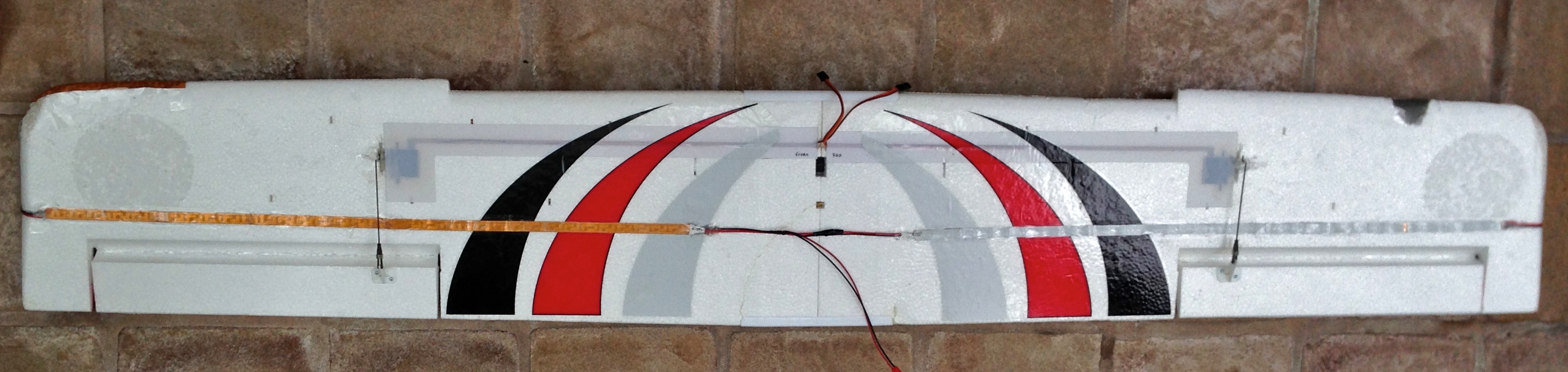
The wing as it looked when I finished installing the LED strips
I also soldered the two LED strips to a common JST BEC connector. But I made a mistake here which was only discovered much later after I crash-landed on grass and partially tore off the wing again – I should have left plenty of slack between the two strips instead of a taut line.
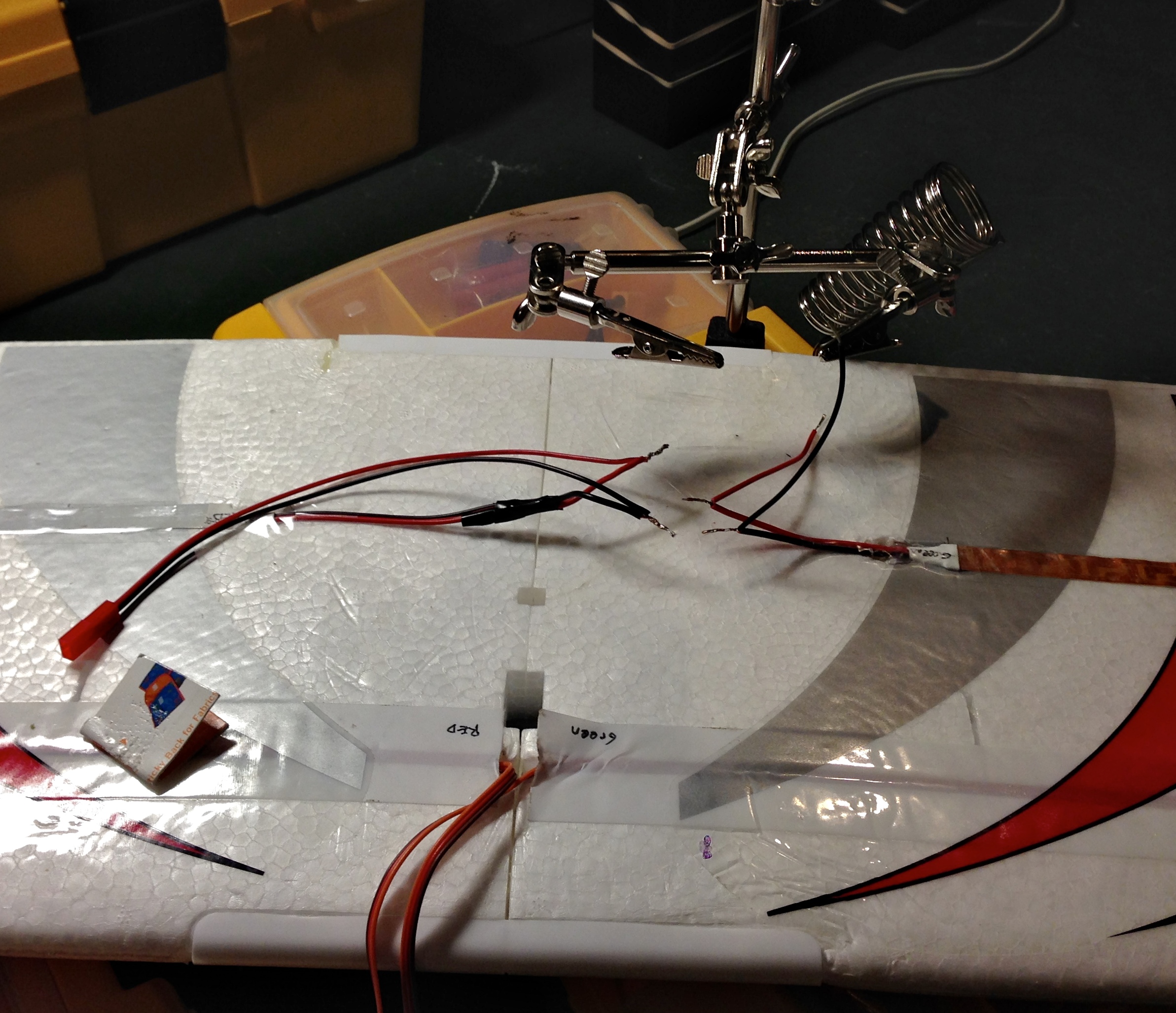
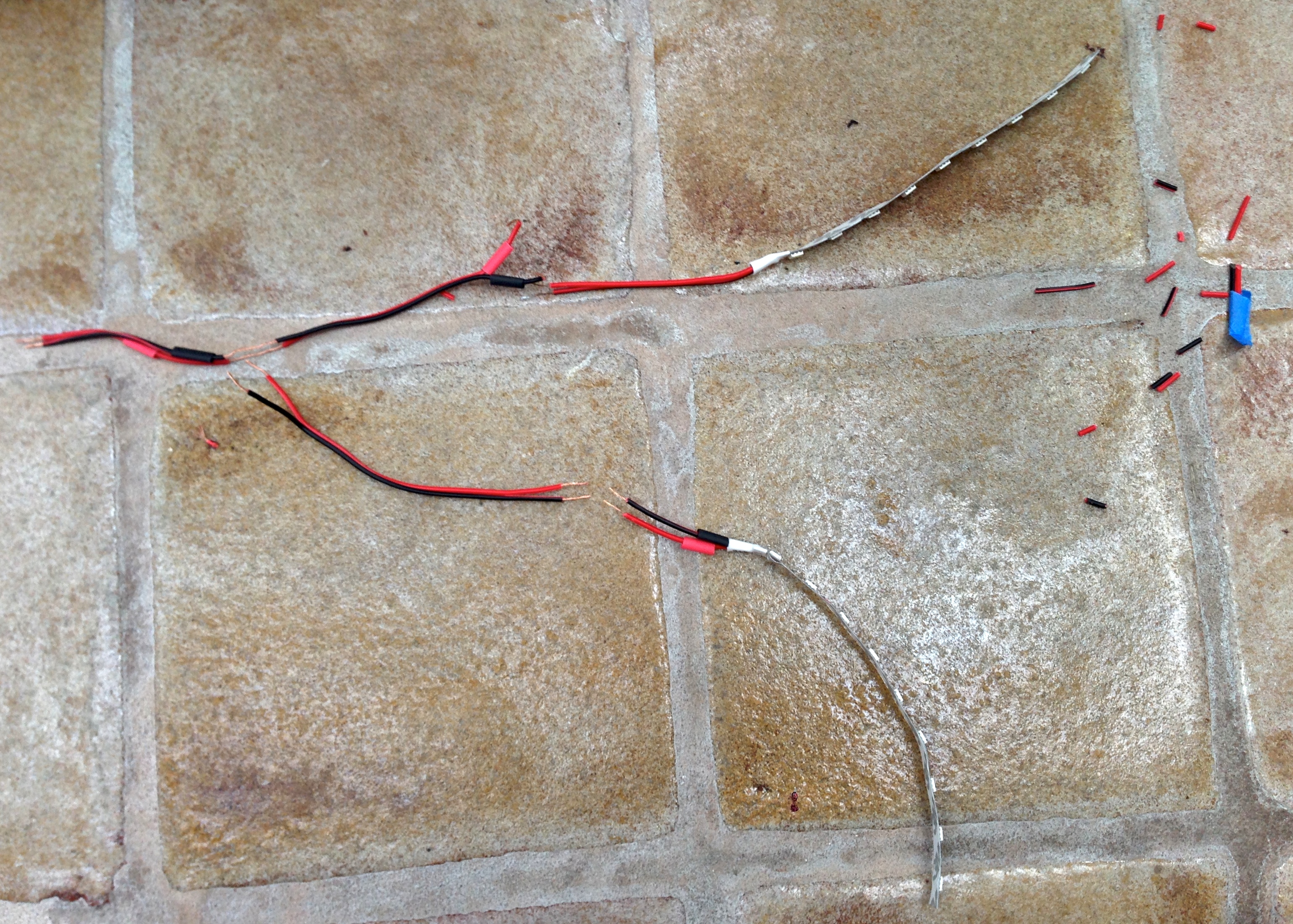
Reshaping wires after a bad landing to give them more slack
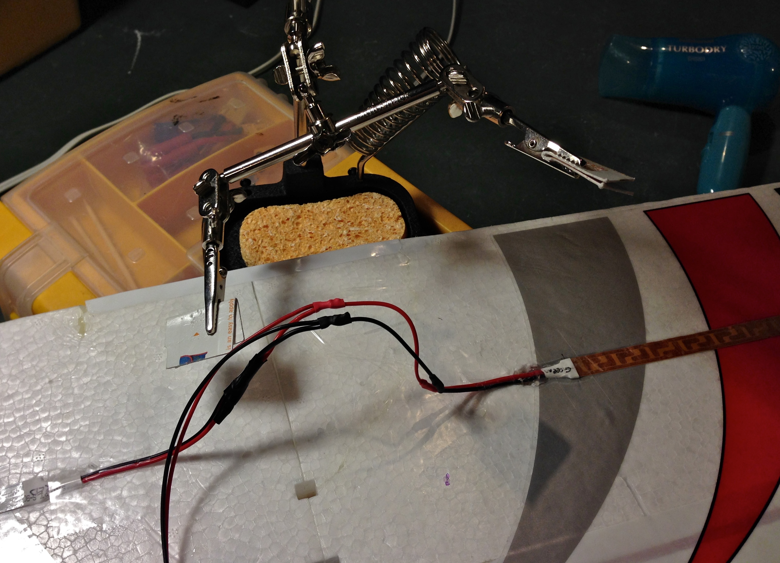
The finished Y-junction that won’t break when the wing flexes
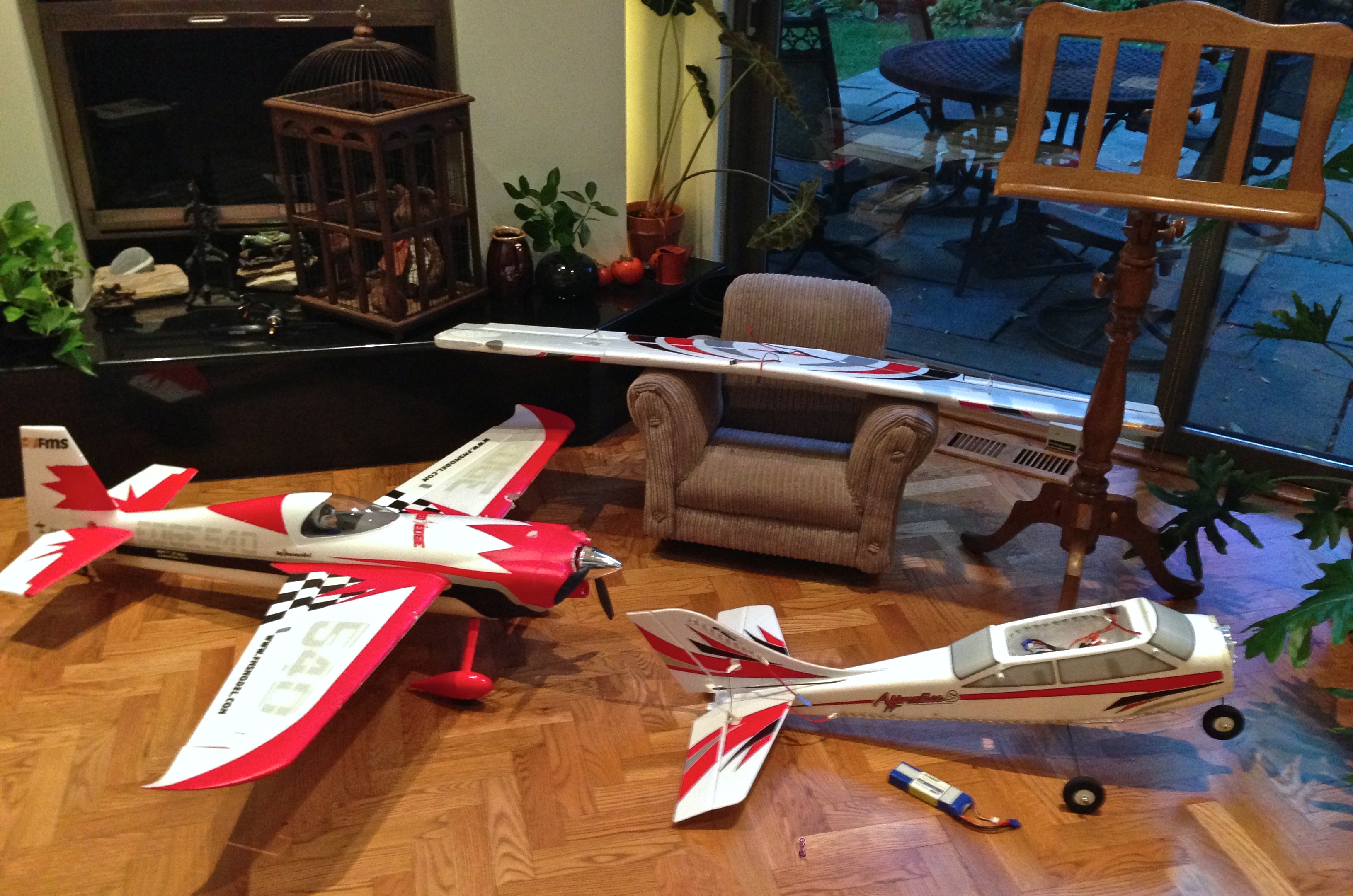
Taking a break
So what I thought would take me two hours took me a day instead. Here I was taking a break as the sun sets. I tested the LEDs on the wing by connecting it to the LED controller. The FMS Edge 540 behind the Apprentice just came back from the dead – a fellow modeler came knocking on my door bearing this gift from the dead. I carelessly flew this plane too close to the edge of the flying field last week. It hit the top of a 40-ft tree and tumbled down to ground level, then rolled into a deep ravine behind the trees. Someone adept at navigating the wilderness found my plane days later. I am surprised it suffered only one broken prop, and a hole on the wing (where it hit the top branch).
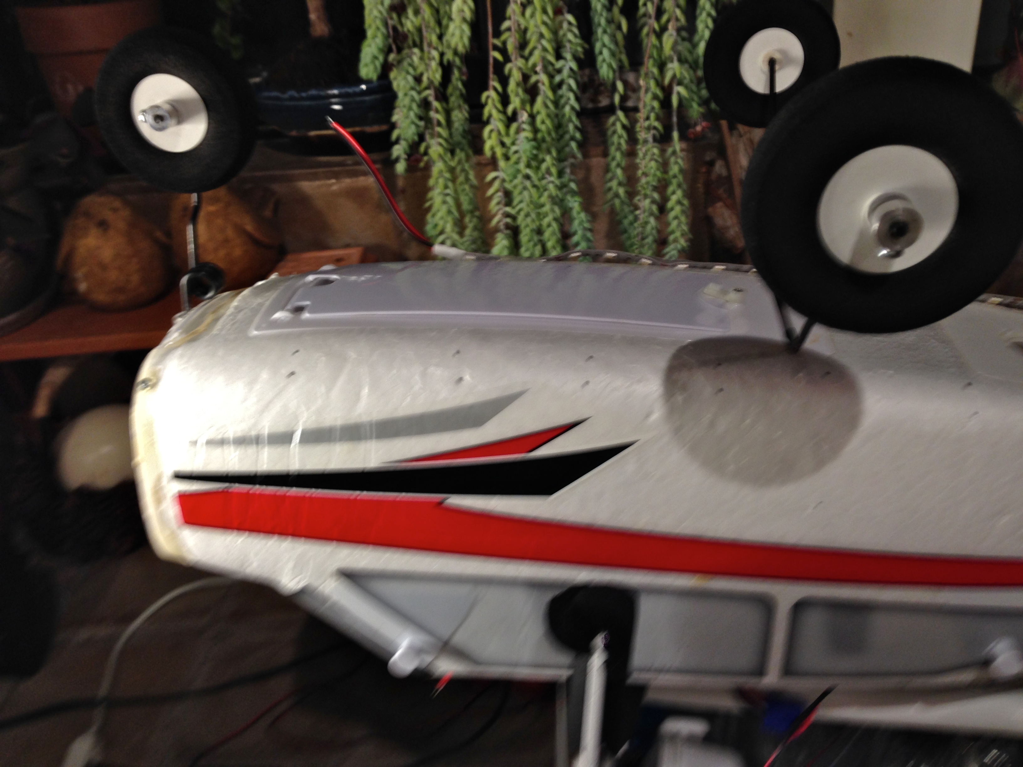
Marking where the groove would go
I turned the plane upside down and sit it on the plane caddy. Then I marked the places where the bottom white LED strip would be mounted, on the right side first.
Etching out a groove using a soldering iron and a metal rule
I took that old soldering iron out again, and etched a groove using a metal rule.
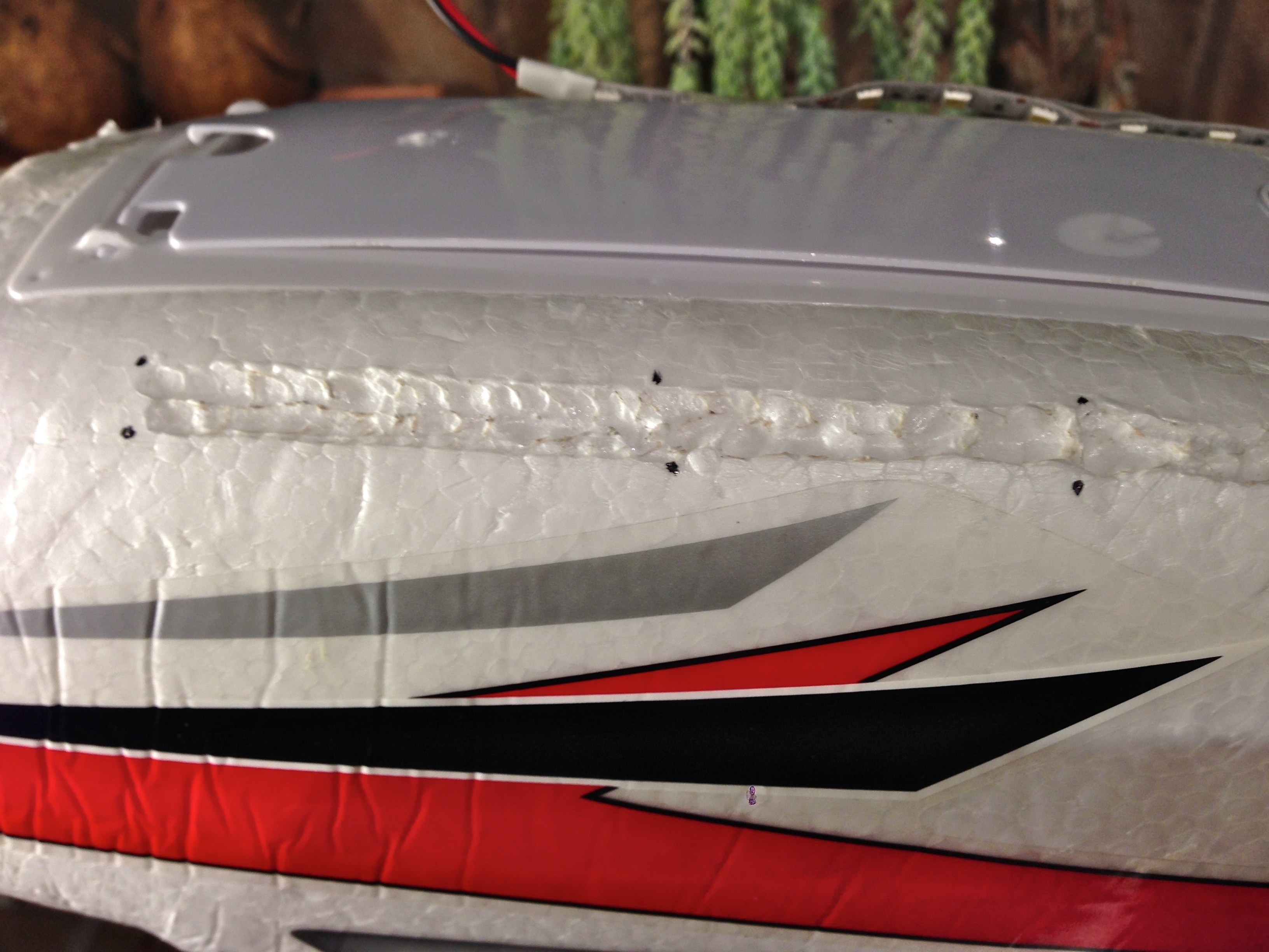
Drop hot glue in between LEDs
I marked the location in between LED lights. That’s were I drop blobs of hot glue. I did not think it was wise to let the glue stand in between the LED and the foam.

Finished strip
White LED strip on one side was firmly mounted flush against the plane surface, between the bottom and the side of the plane.
White LEDs mounted and wired
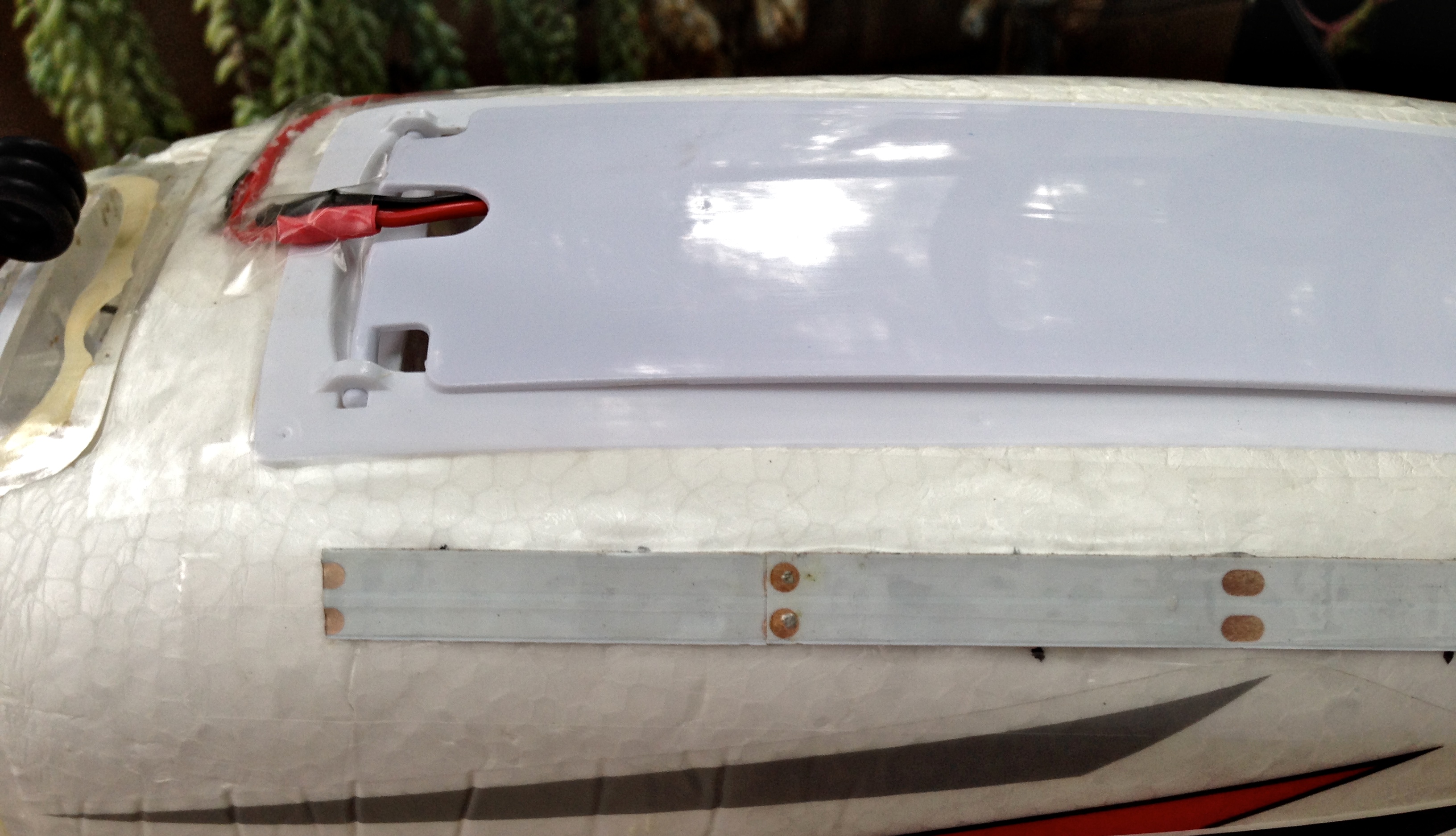
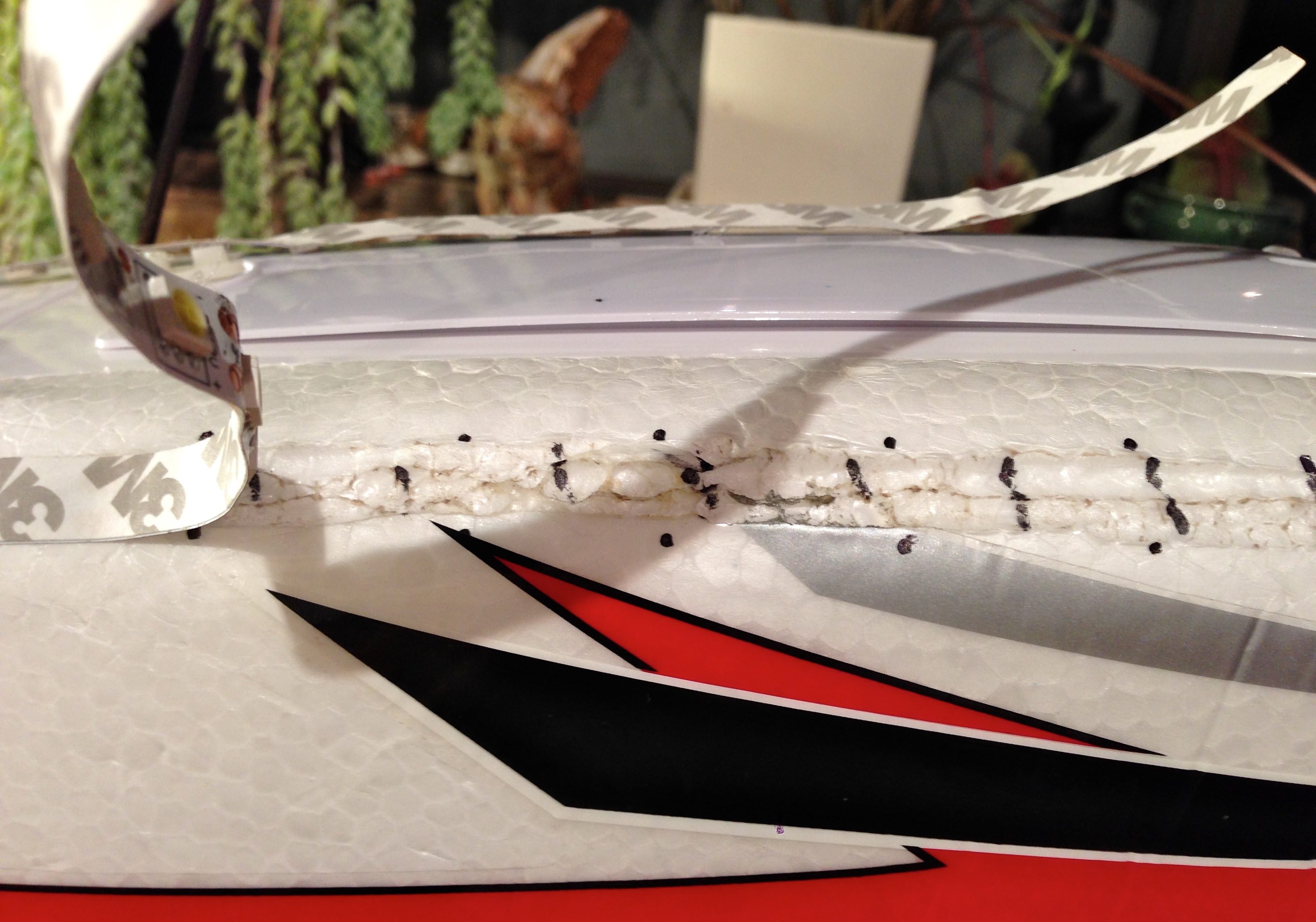
Clear tape laminates the LED strip

The other side
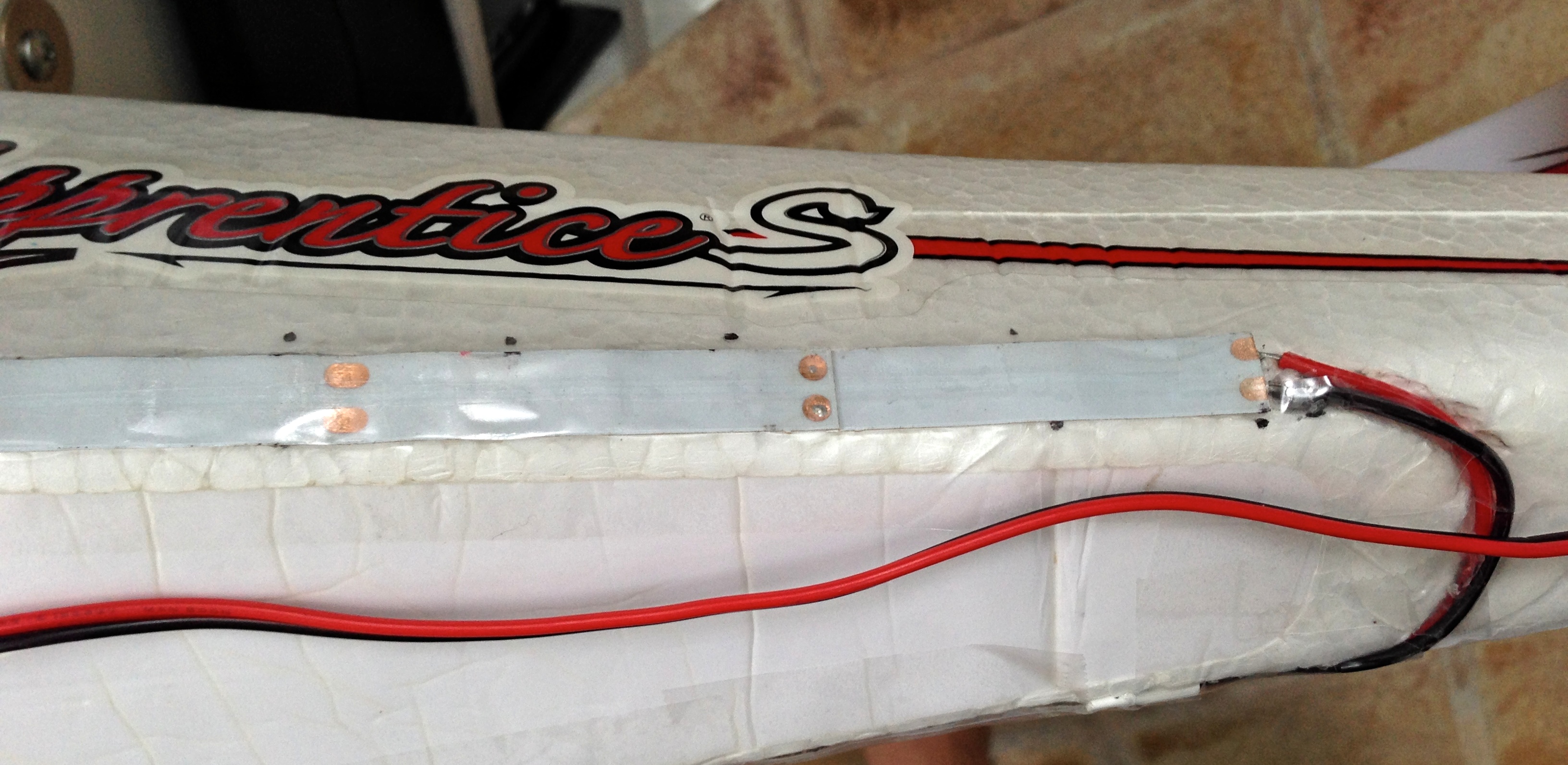
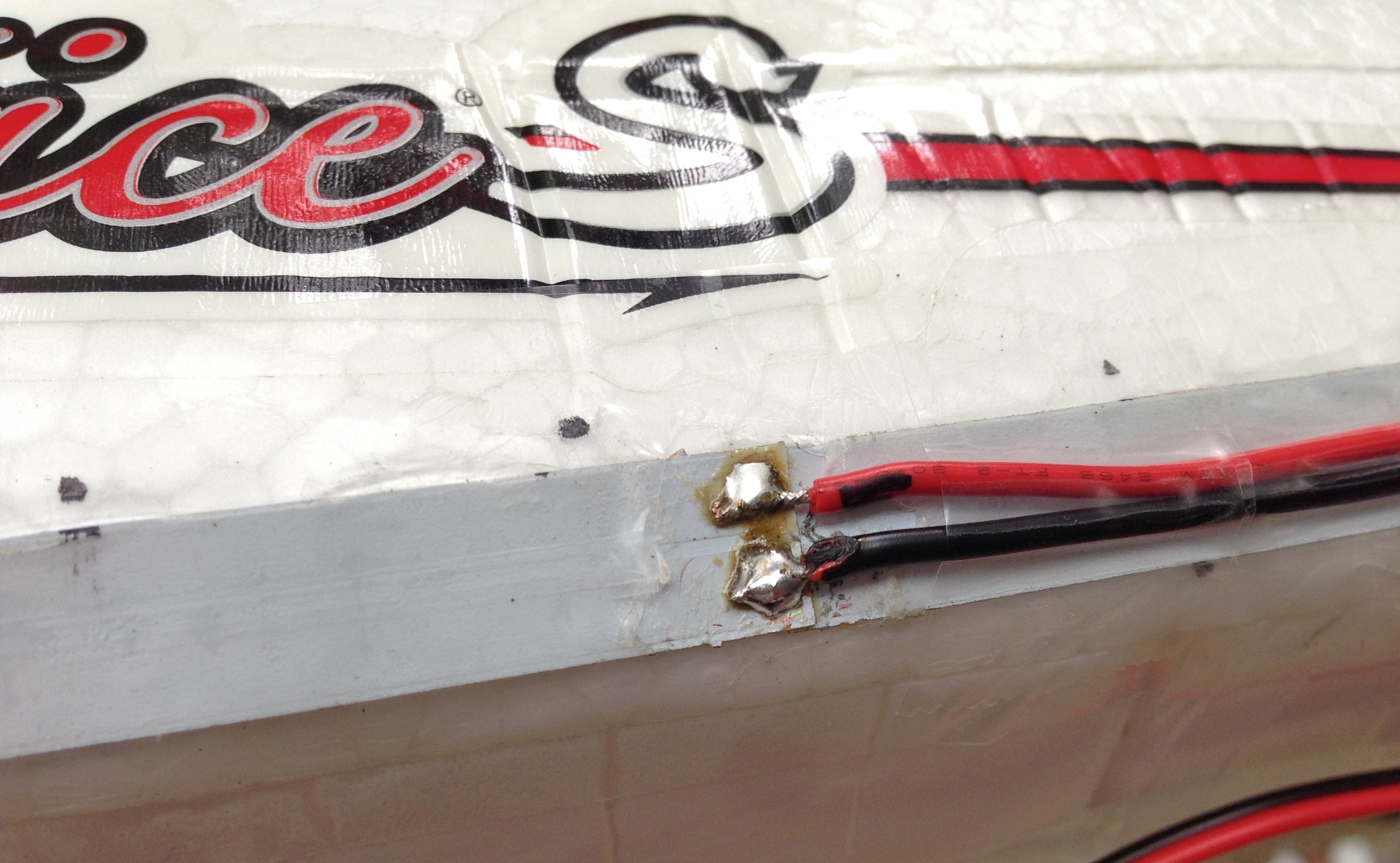
Two strips are connected by a direct solder
I peeled the backing off the LED strip, then taped over its sticky surface as a cheap insurance against bad weather.
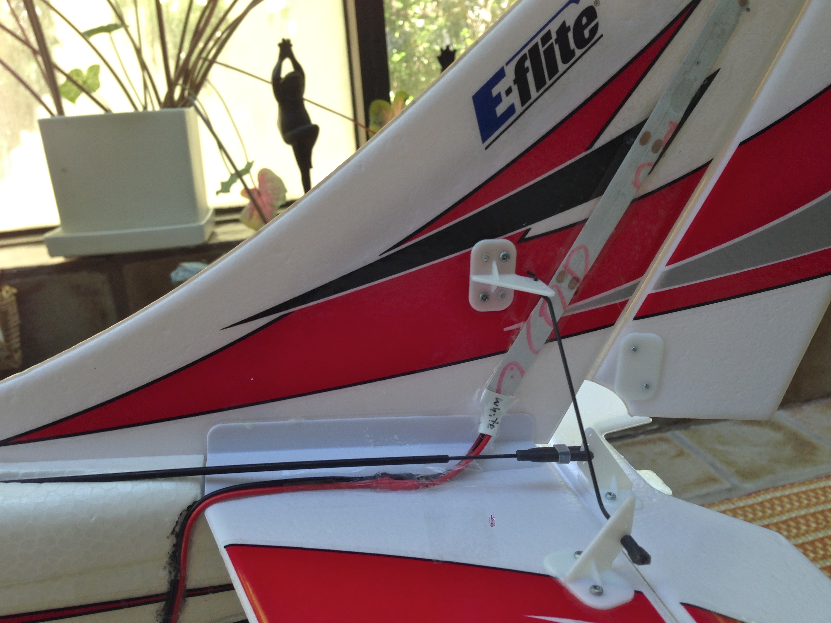
White LED strip on the vertical stabilizer
I wanted to mount white LEDs on the vertical stabilizer. Owners of the Apprentice S must be scratching their head now, wondering about the odd strut between the vertical and horizontal stabilizers in this picture. That was my own earlier addition to the plane, to correct for the feeble vertical stabilizer – I once caused this new stabilizer’s predecessor to be violently shredded midair when I maxed out the rudder surface travel mechanically, and tried to do a real knife edge flight. Sadly, after this addition the plane couldn’t fly at high speed without the Spektrum receiver making over-corrections on the elevator with it built-in and always-on gyro stabilization. I had to install a different receiver without gyros. I suspect that even without the strut addition, these new LED strips would cause similar problems for the factory receiver.
It was amazingly easy to glue these
Gluing this strip to the thin vertical stabilizer turned out to be incredibly easy. The stabilizer was too thin for any groove etching. I tried to pre-imprint LEDs onto the foam before gluing, to make indentations so the strip would mount flush. That didn’t really work. So I gave up and just dab hot glue in between LED lights and pressed the strip down. To my surprise, the hot glue softened the thin foam and the strip sat flush against the stabilizer surface. Now I wonder whether I wasted time etching grooves earlier on the wing and fuselage, only to compromise the structural integrity of the plane, without much gain. Oh well.
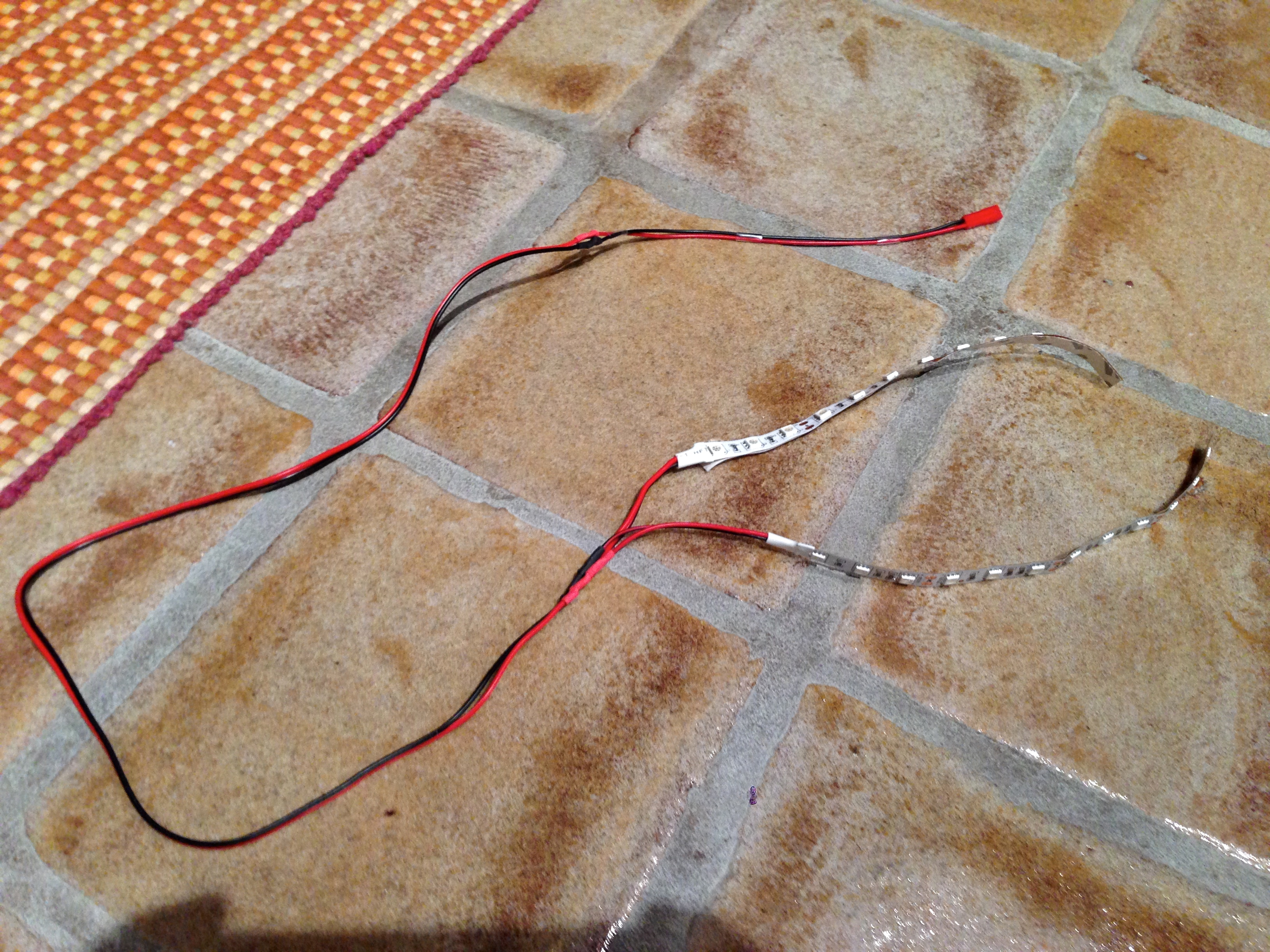
Y-junction for the stabilizer LED strips
I made a Y harness for the lights. At this point I realized that I had forgotten something in the previous step. I was going to have white LEDs on the vertical stabilizer wired to the same output channel as the white LEDs on the belly of the plane. But I’ve not yet soldered these to the strips that were already mounted on the belly.
leeching off the belly strip
I corrected for my earlier mistake by tapping into a connection point on the belly strip.
Y harness for the tail lights
Red on left and green on right
I installed strips on the horizontal stabilizer as well.
Blue LED strips inside the receiver compartment
I hot-glued the a blue LED strip to the inside wall of the receiver compartment. I guess I was a fool to have used a soldering iron to carve out a groove on the wing earlier. Maybe that wasn’t necessary at all. The hot glue was hot enough to melt/soften the foam apparently. But perhaps the lighting effects are different. That’s another investigation for another day.
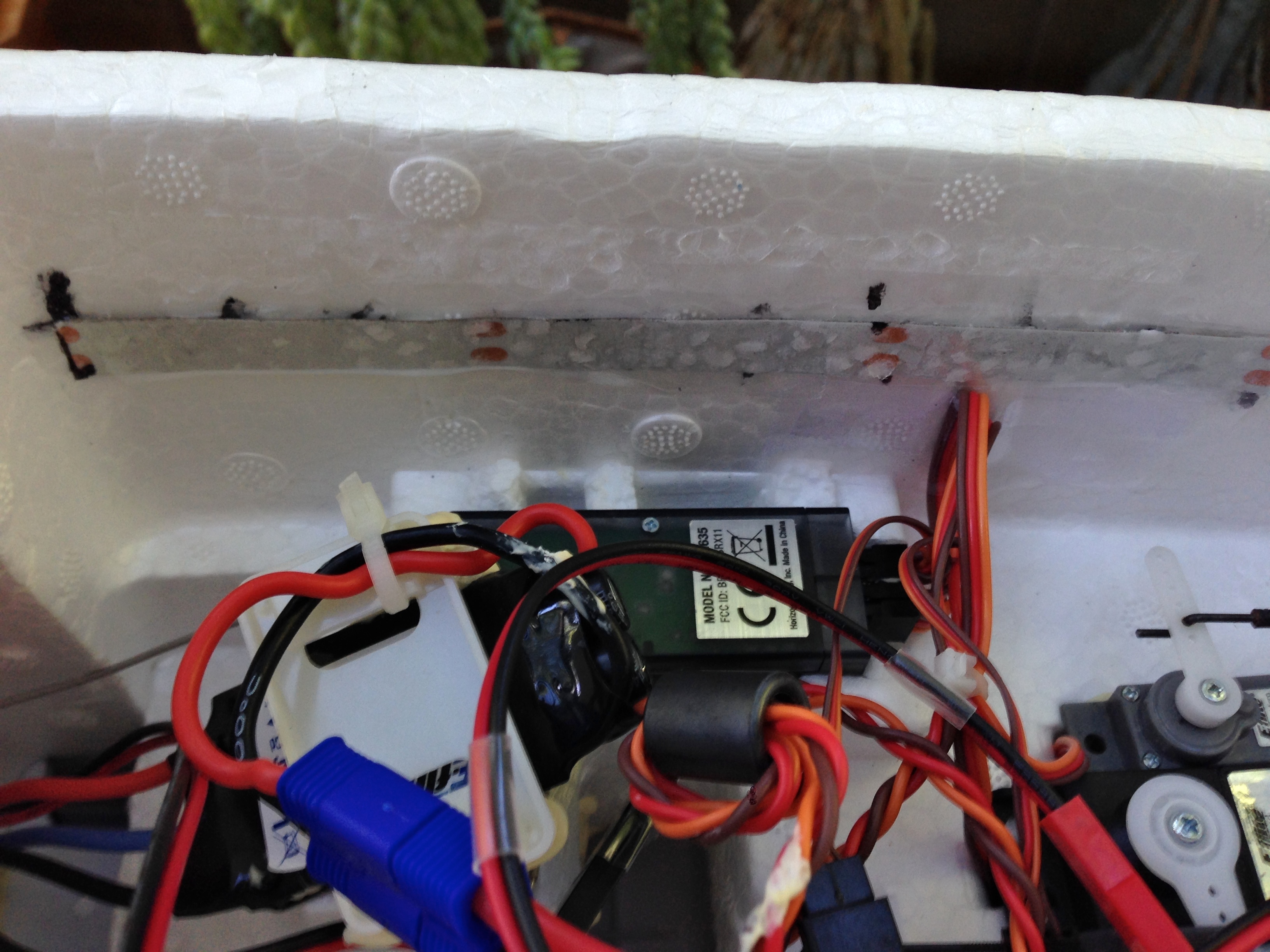
Closeup of the blue strip
Here is a closeup of the strip. It looks fairly flush against the wall.
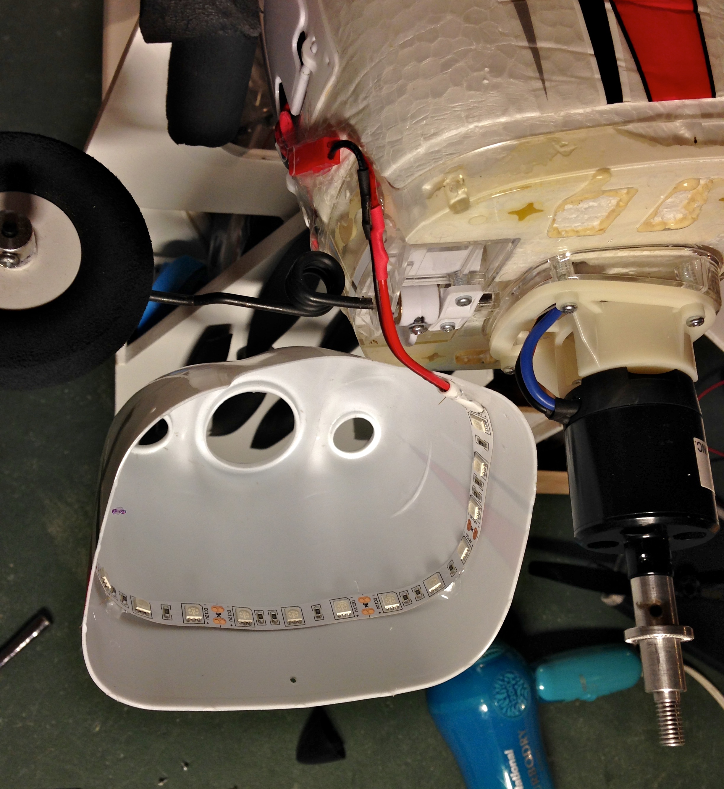
Blue lights inside the cowl
I taped blue LED lights to the inside wall of the cowl. This makes for cool translucent lighting effects. Awesome and easy. This blue strip is Y-connected to the blue strip in the receiver compartment.
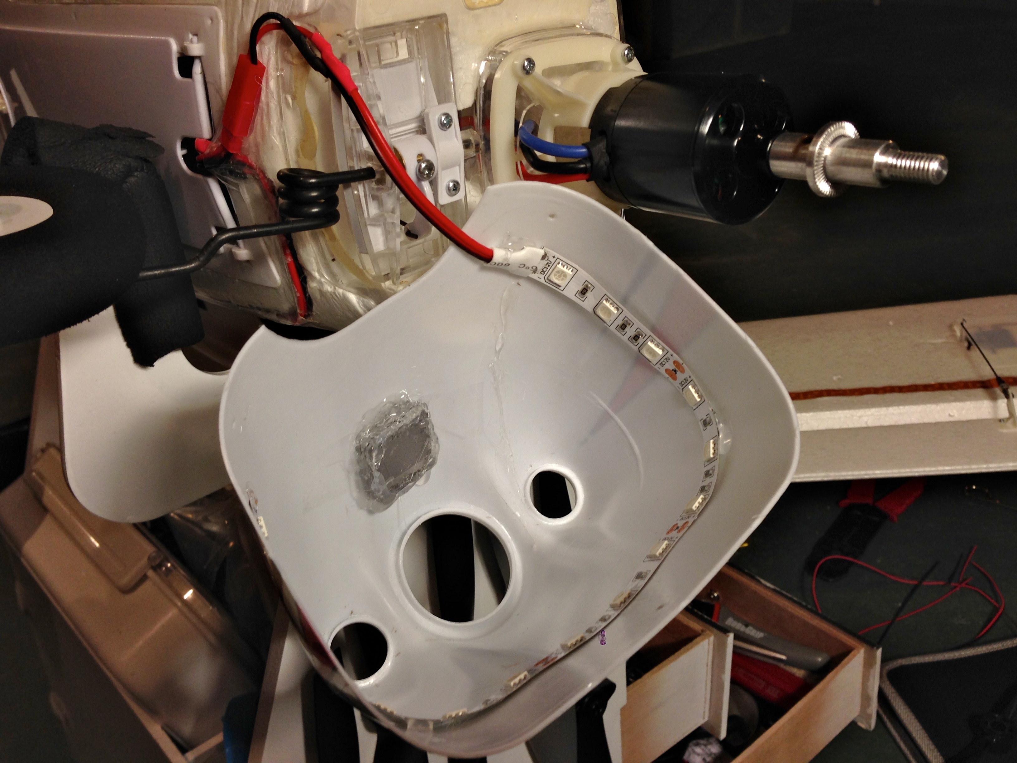
Adding weight to the cowl
The plane was now totally tail heavy, because almost all LED strips, wires and hot glue blobs were located abaft the CG line. I hot-glued some weight to the inside of the cowl, hoping to compensate for this. I applied hot glue blob liberally here, as the idea was to add weight anyway.
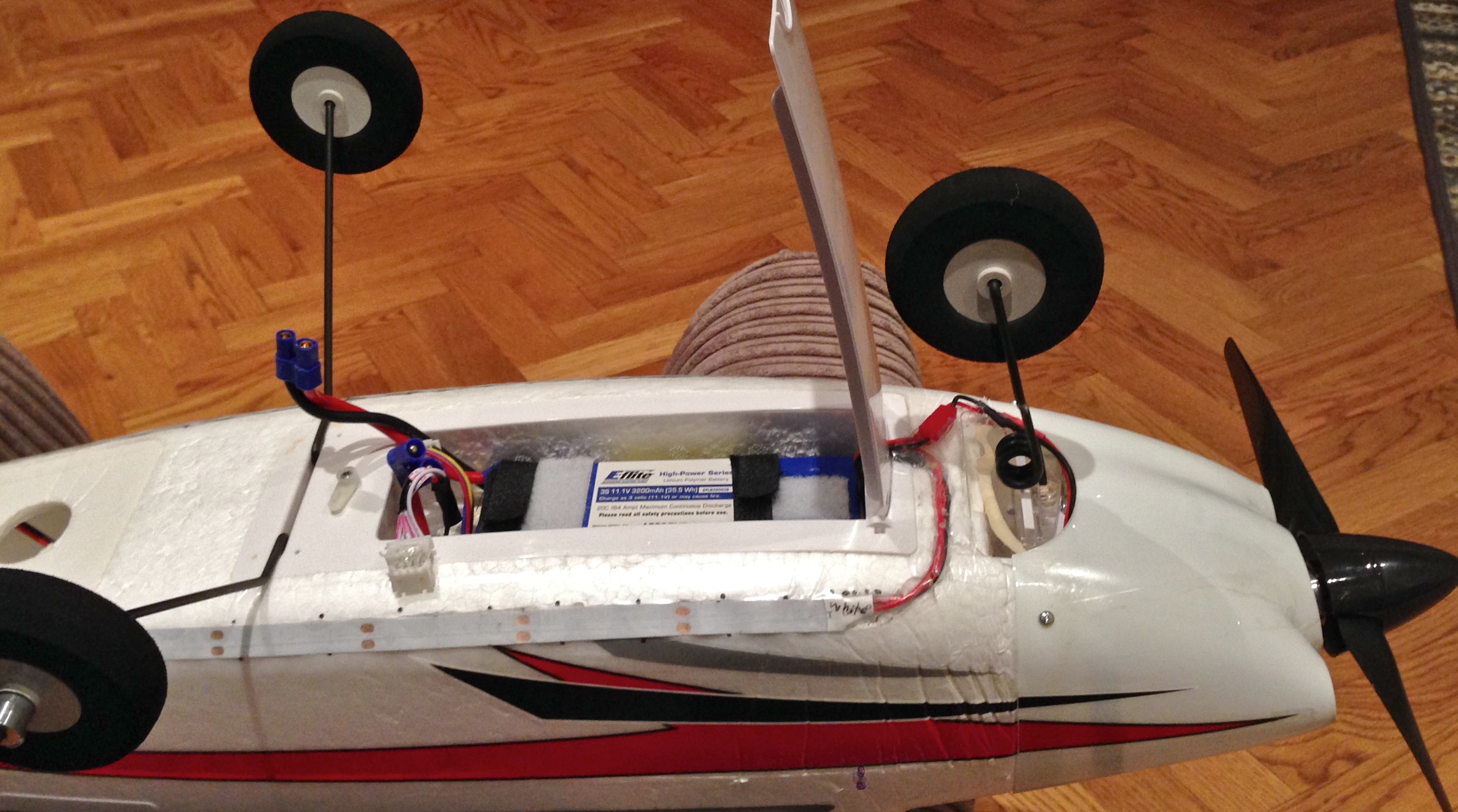
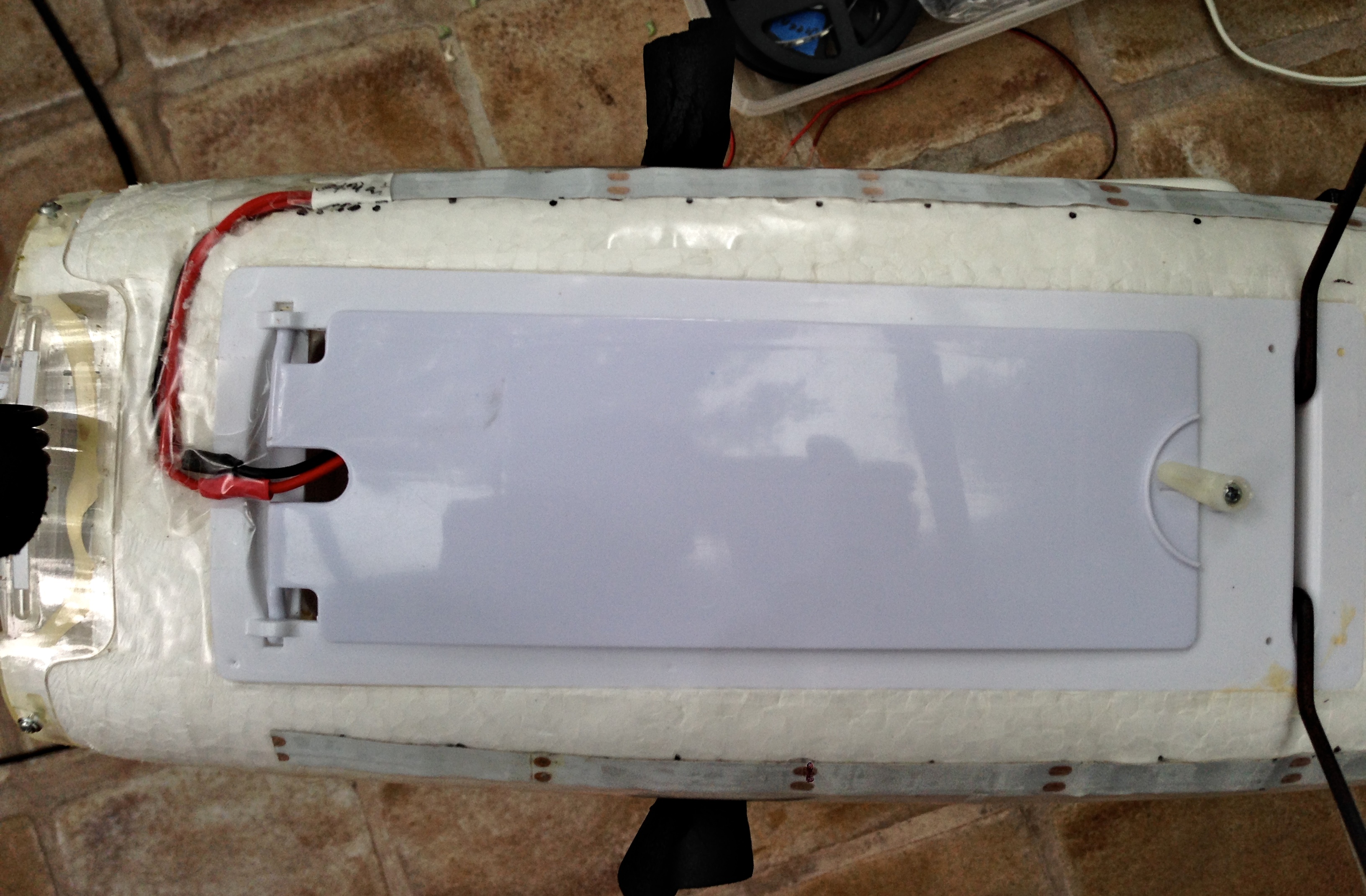
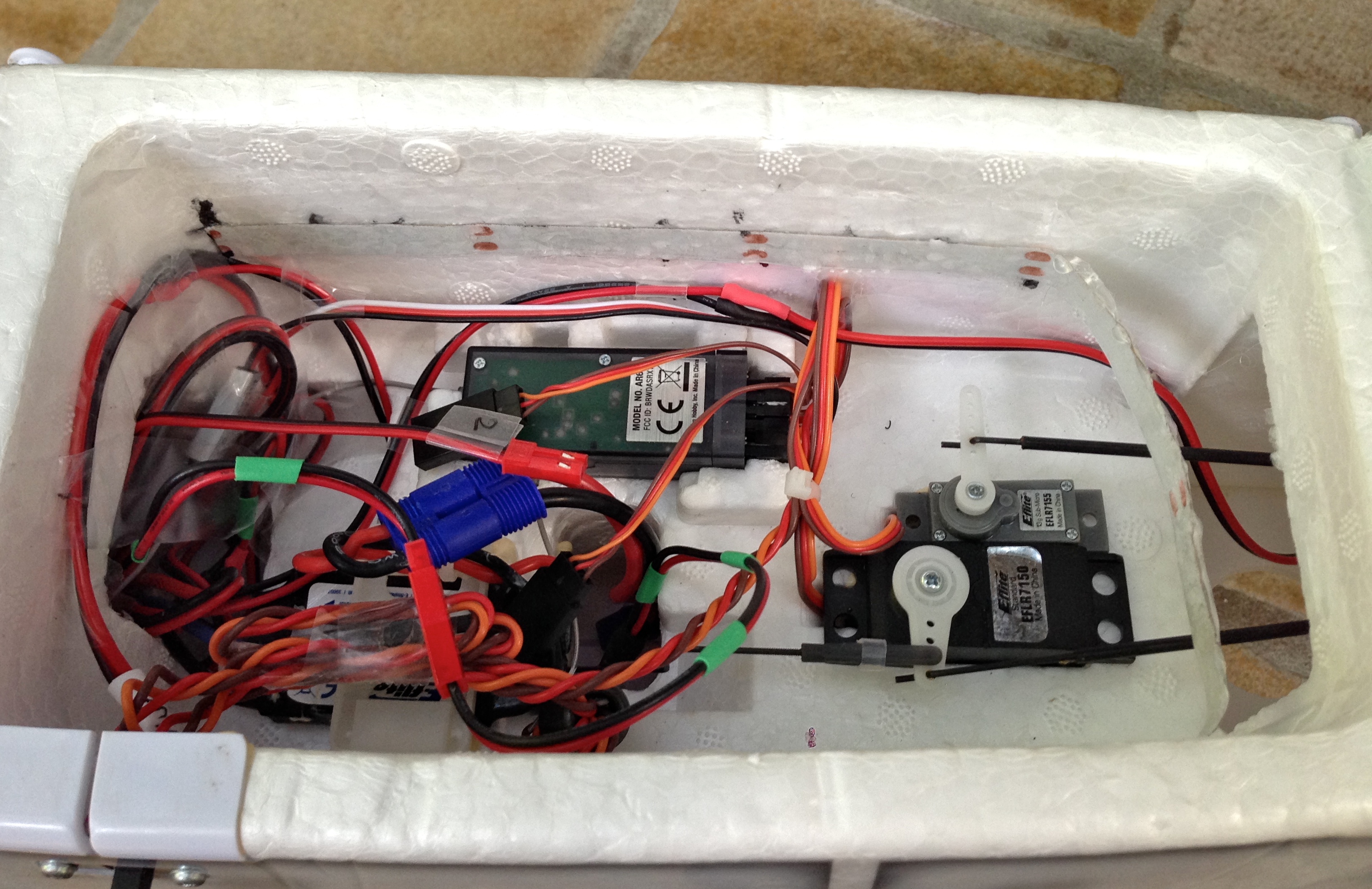
View of the battery compartment
The last piece of work involved the 3S balance connector. I did not want to power the LED controller off the EC3 connector, as I wanted to be able to turn the LED controller off separately, when flying during the day. The easiest way was to tap into the balance connector which remains unused outside of charging. This was how the LED controller was designed to work.
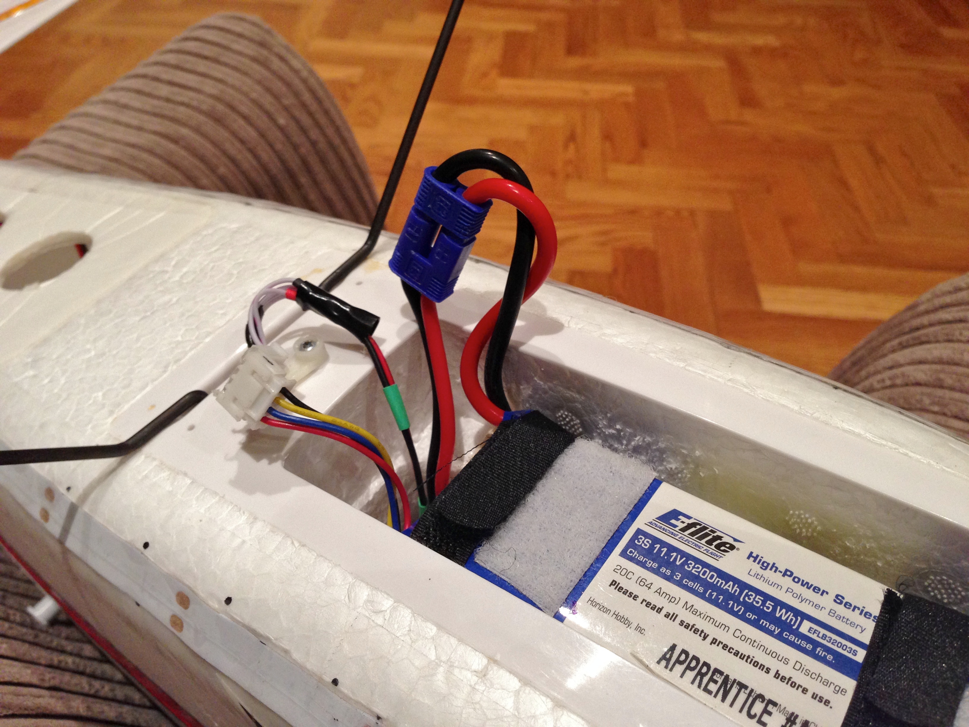
Closeup view of the connectors
But I forgot that the LED controller was to sit in the receiver compartment, while the battery was to be in the bottom compartment. I did not have a spare 3S JST XH connector nor a spare socket lying around to build an extension out of. My local hobby shop didn’t carry JST XH extensions either to my disappointment (one hour wasted in the trip). Not wanting to wait for days for an online order, I unsoldered the 3S socket from the LED controller and made my own extension from the controller to the removed socket.
LEDs at full blast (all on)
Finally, this night-flying machine is ready for prime time. The cowl looks great. In this picture that area is overexposed so it appears whitish, but it really is a cool light blue. The corner lights make the wing looks more substantial than a simple one-dimensional strip. The white LEDs on the belly turn the fuselage into a translucent box. The blue strip inside the receiver compartment turns the top of the plane purplish (these surfaces have been painted/laminated gray on the Apprentice). All colored lights on the wing and stabilizers can be seen from both sides.

View from behind
This picture shows how effective the reverse-mounted LED lights are. Even thought these LEDs are beaming into the foam, enough light leaks or bounces back out to light up the floor.
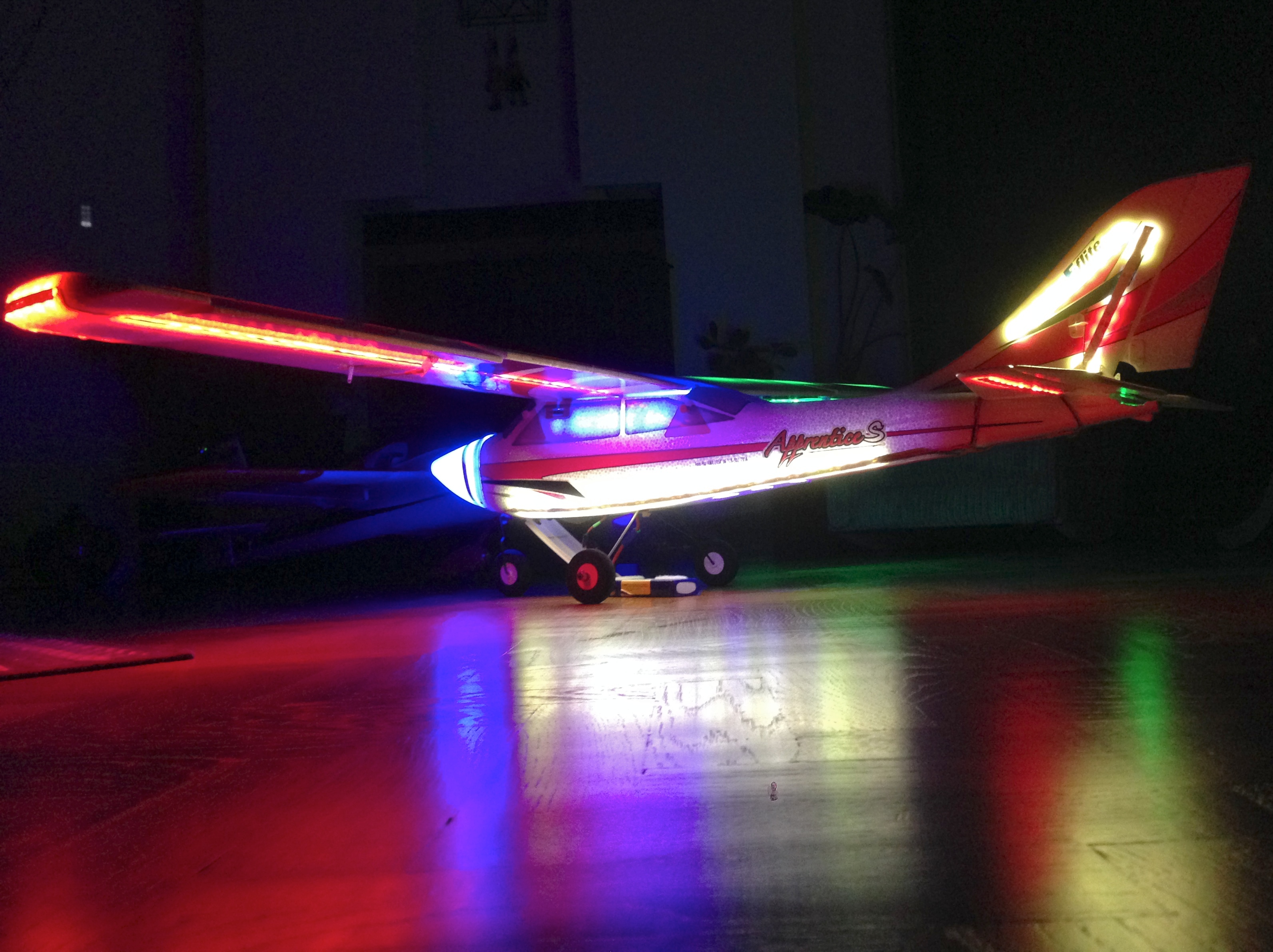
Side view of the plane with all LEDs on
Here is a glorious view of the plane from the side. The cowl, the translucent fuselage and the vertical stabilizer lights allow the pilot to find the orientation of the plane. The red and green strips on the wing and the horizontal stabilizer allow the pilot to judge the angle of the roll in almost all situations. The corner lights on the wing allow the wing to be seen from the side – one can clearly see how effective these reverse-mounted LEDs are at using the foam to diffuse light.
Finally, here is a video showing the light patterns.


Appreciate thiis blog post
ÈðÔ´ ºÜºÃµÄÏ룬ÎÒºÜϲ»¶Äã³£ÓÐеÄÒâ,Ö»ÊÇÎÒ(°üÀ¨²¨Ê¿¶ÙµÄ ÇÓÀÈʾ˾Ë)²»Á˽⣺ΪʲôÄãÒªÓÃÐÁº¥Éú×ö¹PÃû(¾Ë¾ËÎÒ)£¬Ëû³£ÕF\·QÔÞÄãÒ²ºÜÐÀÉÍÄã,µ«ÊǾÍÊÇÓÐHÒÉ»ó,ËûÔøÌá:ÓÃÓÐÔìÁ¦£¬ÐÂ˼ά£¬ÓÐÀíÏëµÄ×ÖÔ~ȥȡÃû£¬þ¸ü¸½ºÏÄãµÄ²ÅÈA²»ÊÇá?ÆäʵËûÒ²ÔÚÎҵĮչÌṩ²»ÉÙ½¨Òé¡£ Íí°²£¡ mom